Introducing MDES: Empowering Data Exchange

MDES provides a common way to exchange manufacturing setup data. It helps different systems share consistent information about tools, fixtures, stock and machine context.

Contact Us

What is the Manufacturing Data Exchange Specification (MDES)?

The Manufacturing Data Exchange Specification (MDES) is an open, industry-focused data-exchange format designed to standardize how manufacturing data is shared across different software and hardware systems in discrete manufacturing.

MDES is a universal digital language for describing physical production assets (such as cutting tools, fixtures, stocks, assemblies and machine setups) so that they can be represented consistently in CAD/CAM, CNC and other manufacturing software. It was introduced by ModuleWorks and is intended to be free-to-use and openly published, so any company can adopt it as a common format.

Vision/Purpose

The goal of MDES is to improve interoperability and eliminate brittle, point‑to‑point proprietary data connectors between different manufacturing systems. By aligning with existing standards such as ISO13399 (cutting-tool data) and DIN4000‑190/DIN4003‑190 (fixture descriptions), MDES creates a unified layer that works across the product lifecycle, from design and planning to machining and quality control.

Practical Benefits

Using MDES helps reduce manual data re-entry, cuts translation errors and supports smoother digital‑thread workflows in CNC‑based and other discrete‑manufacturing environments. It allows tool‑makers, machine OEMs and software vendors to plug into a shared ecosystem instead of maintaining multiple custom interfaces.

Why MDES?

Manufacturers, machine tool builders and CAD/CAM users need MDES because today their data flows are fragmented, fragile and expensive to maintain. MDES unifies and strengthens data exchange, replacing expensive custom bridges with one common “language” for manufacturing assets.

The Core Challenges

1. Multiple proprietary formats

  • Every CAM, CNC, tool library and simulation system has its own way to describe tools, holders, fixtures, stocks, etc.
  • To connect systems, companies build custom, point‑to‑point “bridges” that must be updated whenever a vendor changes something.

2. Data silos and manual re‑entry

  • The same tool or setup is recreated or retyped in different systems (CAD, CAM, machine, simulation), which wastes time and introduces errors.
  • This slows down NC programming, setup on the shop floor, and makes standardization of tooling difficult.

3. Rigid, hard‑to-upgrade IT landscapes

  • Custom integrations make it risky and costly to replace or upgrade a CAM system, a machine controller, or a tool management solution.
  • Many production‑critical machines rely on outdated or proprietary interfaces that do not fit well into modern digital‑thread architectures.

4. Inconsistent and incomplete data

  • Not all systems support the same level of detail (e.g., 3D models, cutting data, collision envelopes), so information is lost when transferring between tools.
  • Lack of standardization makes it harder to guarantee safe, collision‑free machining and optimized cutting conditions.

What MDES Offers as a Solution

1. A common, open data model for equipment

  • MDES defines a neutral format for production equipment (cutting tools, holders, fixtures, stocks, machines, etc.) that any vendor can implement.
  • It aligns with standards like ISO 13399 and DIN 4000/4003, so existing standardized tooling data can be used directly.

2. One connector instead of many

  • Instead of building N×M custom bridges between all systems, each system connects once to MDES and can then exchange data with any other MDES‑compliant system.
  • This significantly reduces time and cost for building and maintaining data bridges and increases flexibility to add or replace systems.

3. Higher interoperability and easier upgrades

  • MDES aims to “untie” data flow from specific vendors and make IT landscapes more modular, so manufacturers can adopt new CAM, tool‑management, or simulation tools faster.
  • Vendors like Autodesk and BobCAD‑CAM have started adopting MDES precisely to streamline data exchange with machines and other software.

4. Better data quality and richer workflows

  • MDES supports detailed, consistent descriptions of tools and setups, which can be used for more accurate simulation, collision checking and process optimization.
  • As more stakeholders use MDES, error rates drop and collaboration across software, machine tools and robots improve.

Concrete Application Areas: CAD/CAM Shops Using MDES

A job shop using a CAM solution, several 5‑axis CNC machines from different builders and a separate tool management system.

Without MDES

  • The programmer defines tools and holders in the CAM software.
  • The same tools must be redefined or imported using custom macros in each machine’s control and in the tool‑management database.
  • When a tool changes (length, holder, new supplier), each system must be manually updated, and custom post‑processors or import scripts often break.

With MDES

  • The CAM software outputs the complete tool and setup information in MDES format as part of the NC programming workflow.
  • The tool‑management system and the CNC machine (via the machine builder’s MDES‑aware software) both consume the same MDES description; no retyping or custom scripts.
  • When the shop adds a new CAM or simulation tool that supports MDES, it can plug into the same MDES‑based data flow without building new proprietary bridges.

Result

  • Less time spent on data transfer and setup, fewer mismatches between CAM and machine, and easier adoption of new software/hardware over time.

Committed Partners

Interested Partners

MDES in Action

What Specific Data Does MDES Exchange Between CAD/CAM and Machine Tools?

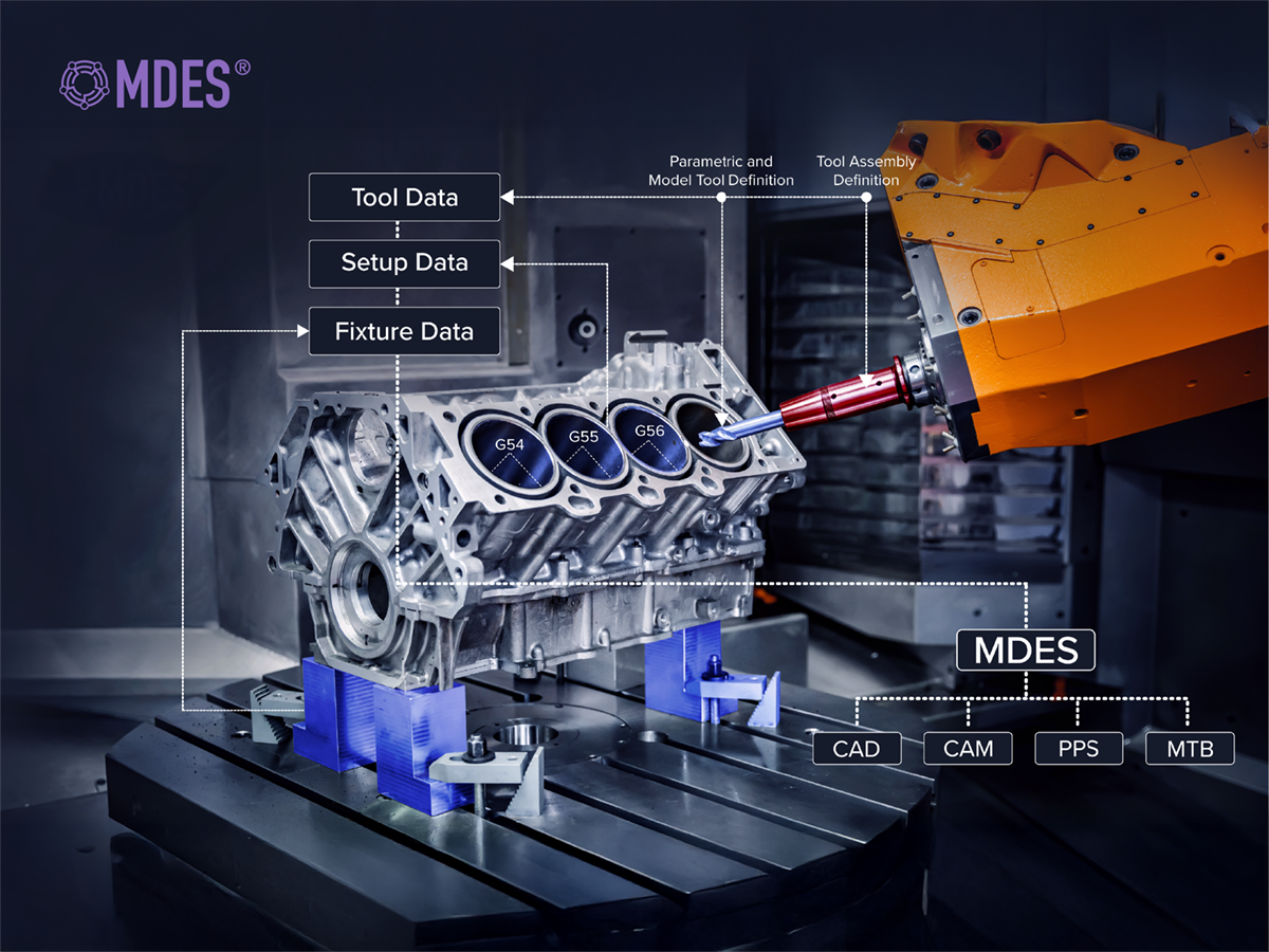
MDES does not send raw G‑code or the full CAD geometry between CAD/CAM and machine tools. Instead, it focuses on exchanging rich descriptions of manufacturing equipment and setups, so both sides “understand” the same digital twin of the process.

1. Tool and tool‑assembly data

MDES describes the cutting tools, holders and full tool assemblies that CAM uses, including

  • Tool part numbers, names, categories and supplier info.
  • Geometry parameters (diameter, length, flute length, shoulder length, corner radius, etc.).
  • Holder and assembly structure (e.g., collet, shank, retention knob) and how tools are mounted together.

This lets the machine‑tool side know the exact physical makeup of each tool that the CAM program assumes, avoiding mismatches between simulated and real tool lengths/diameters.

2. Fixtures, stocks and workholding

MDES also carries,

  • Fixture descriptions (clamps, vices, pallets, custom fixtures) and their mounting positions on the machine.
  • Stock or raw-part geometry and how it is positioned relative to the fixture and machine coordinate system.
  • Workholding setups (what fixture where, which side of the part is machined, vise/plate references, etc.).

This allows the machine control or setup software to visualize the same setup that was planned in the CAM system, which helps avoid collisions and misalignments.

3. Future developments

Further development of MDES is ongoing. In the future, MDES will be able to represent:

  • Machine types and kinematic capabilities (e.g., 3‑axis, 5‑axis, turning‑mill, gantry vs. bridge).
  • Spindle and auxiliary unit definitions (speed, power, coolant, tool‑changer types).
  • How fixtures and tooling are mounted on the machine table or pallet, including offsets and home position

This will enable the CAM system and the machine‑tool control to “agree” on the machine layout and kinematics, which is important for trajectory planning and safe motions.

Why this matters for CAD/CAM ↔ machine communication

By sending these equipment and setup descriptions in a common MDES format, CAD/CAM and machine tools can:

  • Avoid recreating tools and setups manually in each system.
  • Reduce errors in tool lengths, offsets, fixture positions and machine capabilities that would otherwise cause collisions or scrapped parts.
  • Enable richer, more reliable workflows (e.g., simulation, probing and in‑machine verification) because the NC program and the machine control share the same underlying equipment model.

In short, MDES moves the focus from “raw G‑code” to “what is actually mounted on the machine and how it relates to the CAD/CAM model,” using a neutral, open format that both sides can read and trust.

A Practical Use‑Case for MDES in a Collision‑Aware

Machine Tool

There are machine tools with collision deployment systems that can read MDES. Hence, in a world where a machine can protect itself from collisions, importing an MDES file is a fast and easy way to give the system the context of what it is machining along with the inputs related to a part’s geometry. MDES provides input on the tools used, saving around an hour of setup time for collision avoidance systems on the machine tool.

What this setup does

On a machine that has an onboard collision‑avoidance system, the control can automatically protect itself from crashes if it knows:

  • What part is being machined (its geometry and position).
  • New software and equipment can be integrated with less custom development.
  • How everything is arranged on the machine (tables, chucks, pallets, travel limits).

An MDES file provides exactly that:

  • It tells the machine the context of the part (stock, fixture, workholding layout) and the tools and assemblies that will be used in the CAM program.
  • Instead of manually re‑entering or reconstructing this setup, the machine can simply import the MDES file to “understand” the environment that was used in the CAD/CAM software.

Why is this valuable?

  • Saves setup time: Because there is no need to manually configure the collision‑avoidance system (no manual offsets, tool‑length entries, or fixture‑position re‑definition), a one-hour saving in setup time is realistic.
  • Enables self‑protection: With the MDES‑based context, the machine can compare the incoming NC program against the digital twin of the setup and detect or avoid dangerous motions before they happen.

The core purpose of the MDES file

In this world, the purpose of an MDES file is:

  • To give the machine all the context it needs to self‑protect (part geometry, tools, fixtures, machine layout) in a single, standardized import.
  • To eliminate manual recreation of the setup and drastically cut configuration time for collision‑avoidance and simulation systems on CNC machines.

Join the Ecosystem

Get started with MDES today and be at the forefront of the digital transformation in discrete manufacturing. Together, let's shape a more connected and efficient future!

Contact Us!